
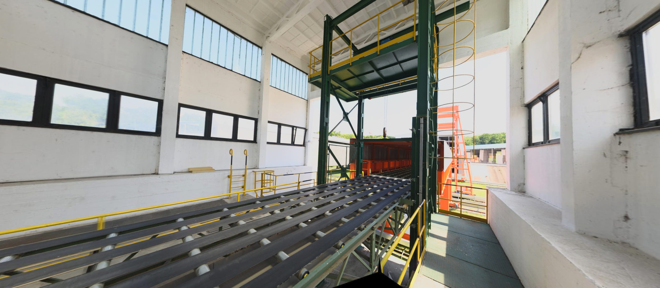
A rail-mounted crane system within an industrial foam production facility required precise geometric adjustment at its building connections. Terrestrial laser scanning was used to capture the external building geometry, crane structure and rails in multiple loading positions, creating a measurable point cloud for distance and angular deviation analysis.
The Project
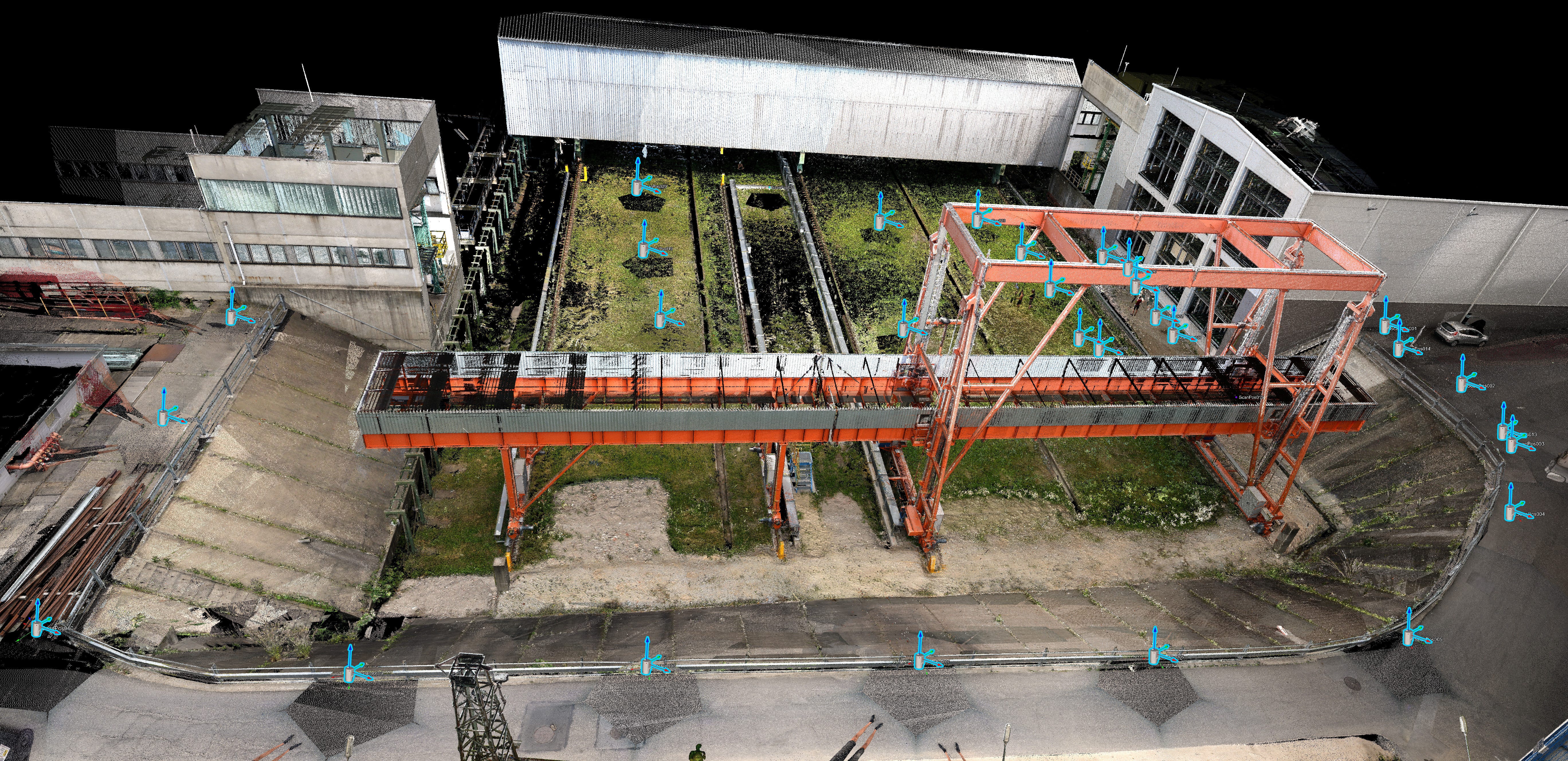
The survey covered approximately 2,500 m² of external industrial space. The goal was to determine the geometric relationship between the surrounding structures, crane system, rails and loading connections, and identify where the system deviated and by how much.
The complex geometry made these deviations difficult to establish reliably using conventional surveying methods, while laser scanning preserved the complete spatial relationship in a single measurable dataset.
Capturing a Moving System
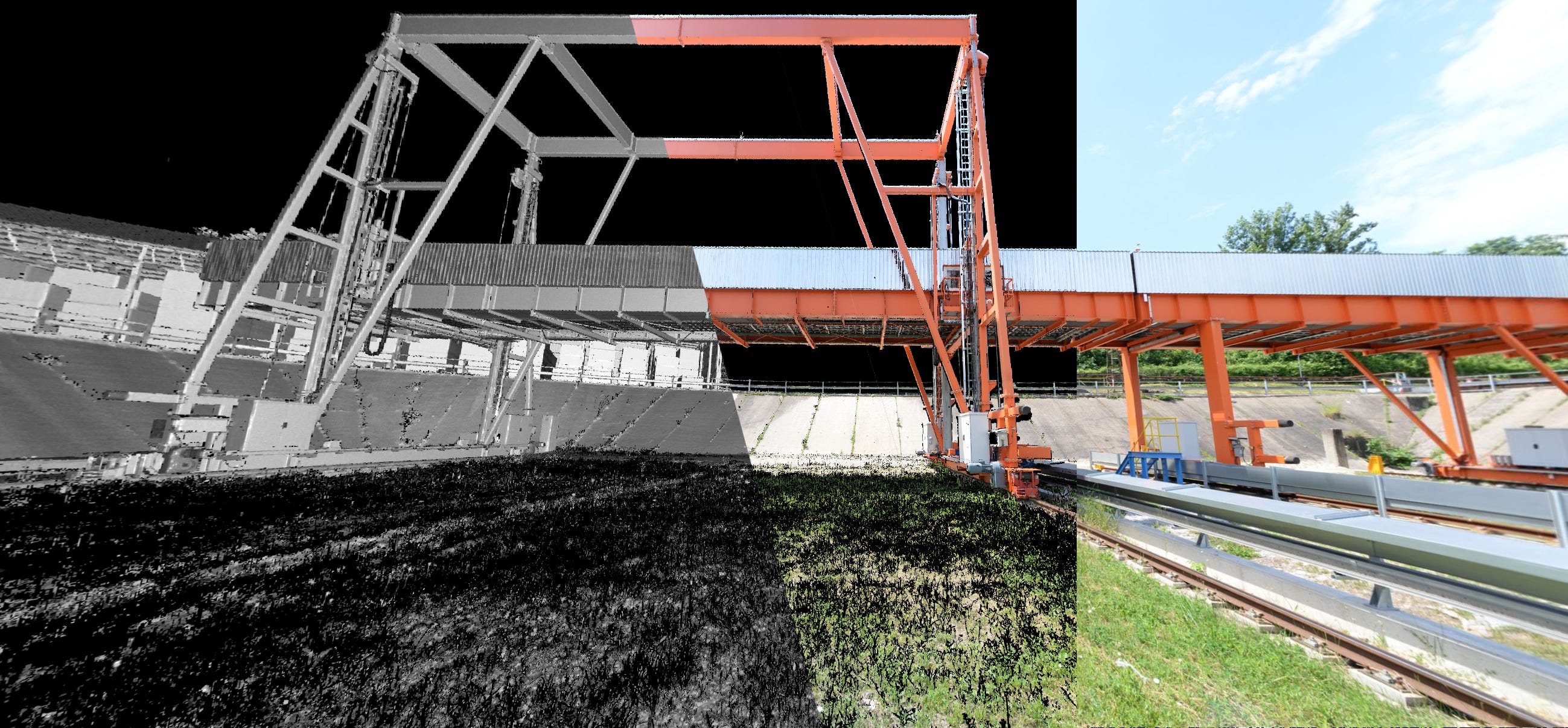
The crane had to be captured in several positions, including connections to six loading openings at one storage section.
The facility remained operational, while the crane itself was stopped during each measurement. A technical supervisor coordinated its repositioning between scans.
The complete field survey was carried out independently in one day using a RIEGL VZ-400i, from 31 scan positions.


From Point Cloud to Engineering Data
The scans were registered, cleaned, colourised and optimised in RiSCAN PRO, producing a unified point cloud with approximately 3–5 mm registration accuracy.
The dataset was used to analyse rail alignment, angular deviations, structural distances, loading connections and the geometry of the 36-compartment curing-area connections.
Distances were evaluated at millimetre level and angular deviations to 0.1°. The findings were presented in 15 annotated deviation views.


The Result
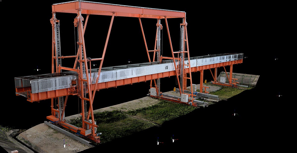
The final delivery consisted of a registered colour point cloud in LAS format and 15 graphical deviation analyses.
The measurements provided the design team with the geometric basis needed to adjust the crane and rail system, without an additional site visit.
The project turned complex captured geometry into directly usable engineering information.
Project at a Glance
1 day — Field survey
31 — Scan positions
1.6 billion — Captured points
3–5 mm — Registration accuracy
15 — Annotated deviation views
0 — Additional site visits
The Takeaway
A laser-scanning project does not always need to end in a BIM model.
Here, the point cloud itself became the engineering environment for measurement, analysis and realignment.
Capture → analyse → adjust.
Planning a Complex Industrial Reality Capture Project?
Need accurate existing-condition data for a complex industrial structure? Let’s discuss the right reality-capture approach.
Point Cloud Processing →
Reality Capture Support →

